- HOME
- WHAT’S NEW
- PRECISION MEASUREMENT
- LCR Bridge 6451-2 with Limits Comparator
- PRESSURE MEASUREMENT
- POWER PLANT
- RESISTANCE MEASUREMENT
- MO-5889-200A Portable Digital Micro-ohmmeter
- MO-5890-200A Portable Digital Micro-ohmmeter
- MO-5893-10A Portable Digital Micro-ohmmeter
- MO-5893-10AT Portable Digital Micro-ohmmeter
- MO-5898-100A Portable Digital Micro-ohmmeter
- MO-5898-200A Portable Digital Micro-ohmmeter
- MO-5899-100A Portable Digital Micro-ohmmeter
- Resistance Test Clamp
- Kelvin Test Lead Sets
- Model 5894 Wide Range Precision Ohmmeter
- Model 5896C Dual Channel Transformer Micro-Ohmmeter (RM)
- Model 5898 Portable 200A Precision Micro-Ohmmeter (RM)
- Standard Reference Resistors
- PORTABLE BRIDGES
- DECADE RESISTANCE BOXES
- TRANSFORMER TEST EQUIPMENT
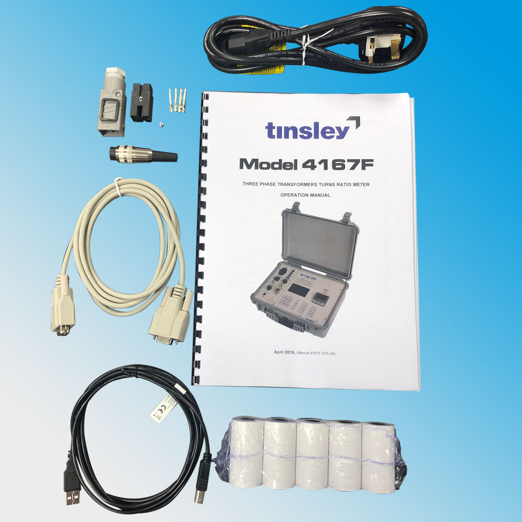
- Portable Transformer Ratiometer Model 4167F
- Portable Transformer Ratiometer Model 4167F-(CVT)
- Portable ‘Q’ (Quality) meter type 5867
- Transformer Micro-Ohmmeter (10 Amp) 5895
- Dual Channel Transformer Micro-Ohmmeter 5896C
- High Current (100 Amp) Portable Micro-Ohmmeter 5897
- High Current (200A) Portable Micro-Ohmmeter 5898
- High Resistance Fault Locator 5762N
- PORTABLE TEST & MEASUREMENT
- SUBMARINE CABLE TEST
- Long Haul Submarine Cable Test Set Model 5903
- Portable Short-Haul Submarine Cable Test Set Model 5910
- Short Haul Submarine Cable Test Set Model 5910R (Rack Mount)
- Electroding Generator Model 5915
- Electroding Detector Model 5916
- Beach Probe & Battery Powered Portable Electroding Detector Models 5917 and 5918
- Cable Termination Unit Type 5941
- Cable Termination Unit Type 5941-3 LAN
- P1000E Earth Probe
- DIGITAL EARTH TESTER
- OBSOLETE PRODUCTS
- HISTORY
- CONTACT
QUESTIONS? CALL: 01376 335271
![]()
Tinsley offer a wide range of products ranging from transformer testers to submarine cable equipment
T 01376 335271
Email: info@tinsley.co.uk
Tinsley Instrumentation Ltd
1 Warner Drive, Springwood Industrial Estate, Braintree, Essex CM7 2YW
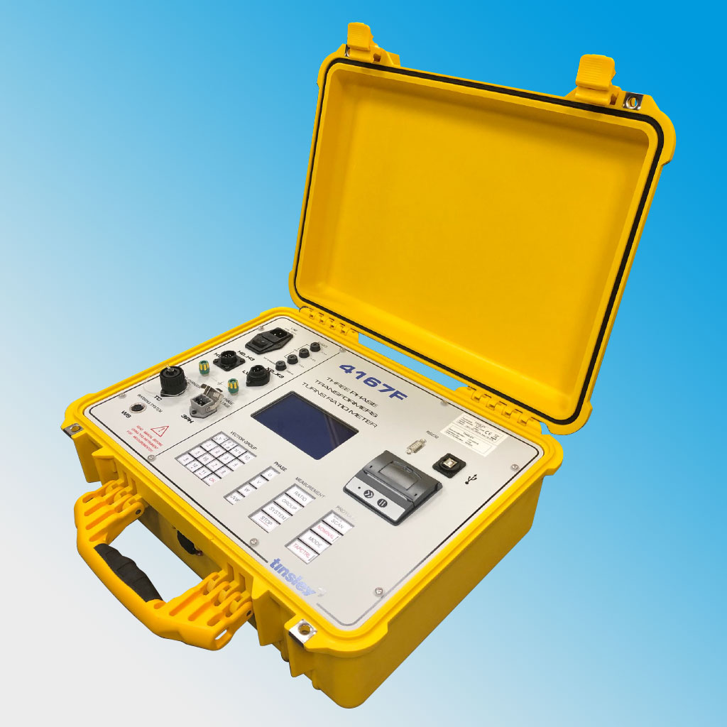
Portable Transformer Ratiometer Model 4167F
See the table below for a run-down of this product's technical data.
Ratio measurement
Range |
Range 0.75 – > 10,000 : 1 |
Max. errors (0,75 .. 2.500) |
± 0.1 % ± 1 d at 40 V .. 200 V
|
Max. errors (2.500 .. 5.000) |
± 0.2 % ± 1 d at 40 V .. 200 V
|
Max. errors (5.000 .. 10.000) |
± 0.3 % ± 1 d at 80 V .. 200 V |
Max. errors (> 10.000) |
not specified (200 V) |
Measuring voltage |
8 V, 40 V, 80 V, 160 V selectable or by external source (8V .. 240 V) |
Measuring frequency |
45 Hz – 65 Hz (Line depended) |
Range selection |
full automatic |
Phase angle measurement
Range (one phase) |
- 9.9 ° to + 9.9 ° |
Range (three phase) |
- 179.9 ° to + 180 ° |
Max. error |
± 0.1 ° ± 2 digit |
Magnetising current measurement
Range |
1 mA – 2000 mA ± 1 % |
Multiplexer
Connections OS |
1U, 1V, 1W, 1N, (H0..H3) Amphenol |
Connections US |
2U, 2V, 2W, 2N, (X0..X3) Amphenol |
Connections ext. excitation |
8 V – 240 V AC, STASEI 5 |
Error detection
Contact-,Stability errors |
displays: HV/LV too low or too high, HV/LV interchanged and bad line stability |
Set point input |
using front keys, via RS232 or chip card |
Deviances |
shown on display, via RS232 |
Start of measurement |
using front panel, via RS232 |
Display |
256 x 128 pixel LC display, back light |
Result format |
vector group, actual phase, actual tap-position, ratio and deviation,
|
Measuring Time |
5 ... 20 s depending on line noise/distortion |
Measurement Storage |
200 sets of measurement data on chip card |
Correct Connection |
tested before each measurement |
Ports |
RS232C (full device control) printer (parallel, ANSI standard) |
Temperature |
Operating: 0° .. 50°C Storage: -5° ... 60°C |
Humidity |
0 ... 90% (Storage 95%) non condensing |
EMC, Safety, Vibration |
CE , IEC-1010-1 , ASTM D 999.75 |
Dimensions |
490 x 400 x 190 mm (WxDxH, mobile ABS rugged case) |
Weight |
approx. 12 kg without cables (mobile version) |
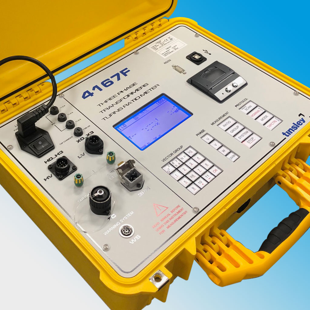
Setting up the instrument is a simple case of typing in the vector group using the instrument front panel keypad and connecting to the offline transformer. All three phases are measured consecutively
with connecting and short circuit procedures at the primary and secondary voltage terminals performed automatically before each measurement. It is also possible to measure just one phase if required.
An adjustable set value permits the display of any error or deviation from the required transformation ratio. It is also possible for the 4167F to control the transformer tap changer and in this case all phases and taps are measured consecutively. Results can be stored internally using a transformer specific memory card, printed to an external printer or transferred to a PC via an RS232 interface.
By using a memory card, pre-programmed for a specific transformer type, the instrument can be made to show a PASS / FAIL message with the actual reading.
The transformer specific memory cards can be easily programmed via a personal computer using the built in card reader or by a cost efficient external card reader/writer directly connecting to a personal computer.
A market unique feature is the automatic vector group detection. If all connections to the transformer have been made, the correct vector group will be detected. In case of missing a connection (1N or 2N e.g.) there will be up to three possible vector groups displayed to the user. Once the correct vector group has been selected the instruments learns this and that group will be presented first next time.
The 4167F is connected to the H.V. and L.V. windings via four connections each. It also powers the transformer at a preset voltage supplied by an internal isolating transformer. However, external excitation using different voltages and frequencies is also possible. is its simplicity to set-up.
The 4167F is housed in a robust carrying case. All connections are provided at the front panel of the instrument and are locked in order to avoid accidental disconnection during a measurement. An alarm-warning lamp is also available and will illuminate whilst a measurement is in progress.
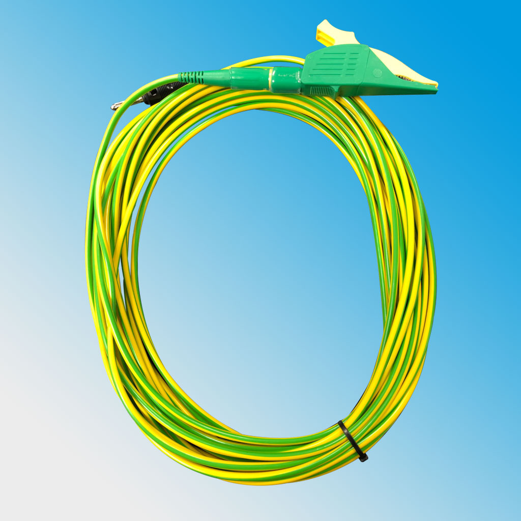
- Warning light: The warning light shows if voltage appears on the test object during measurement.
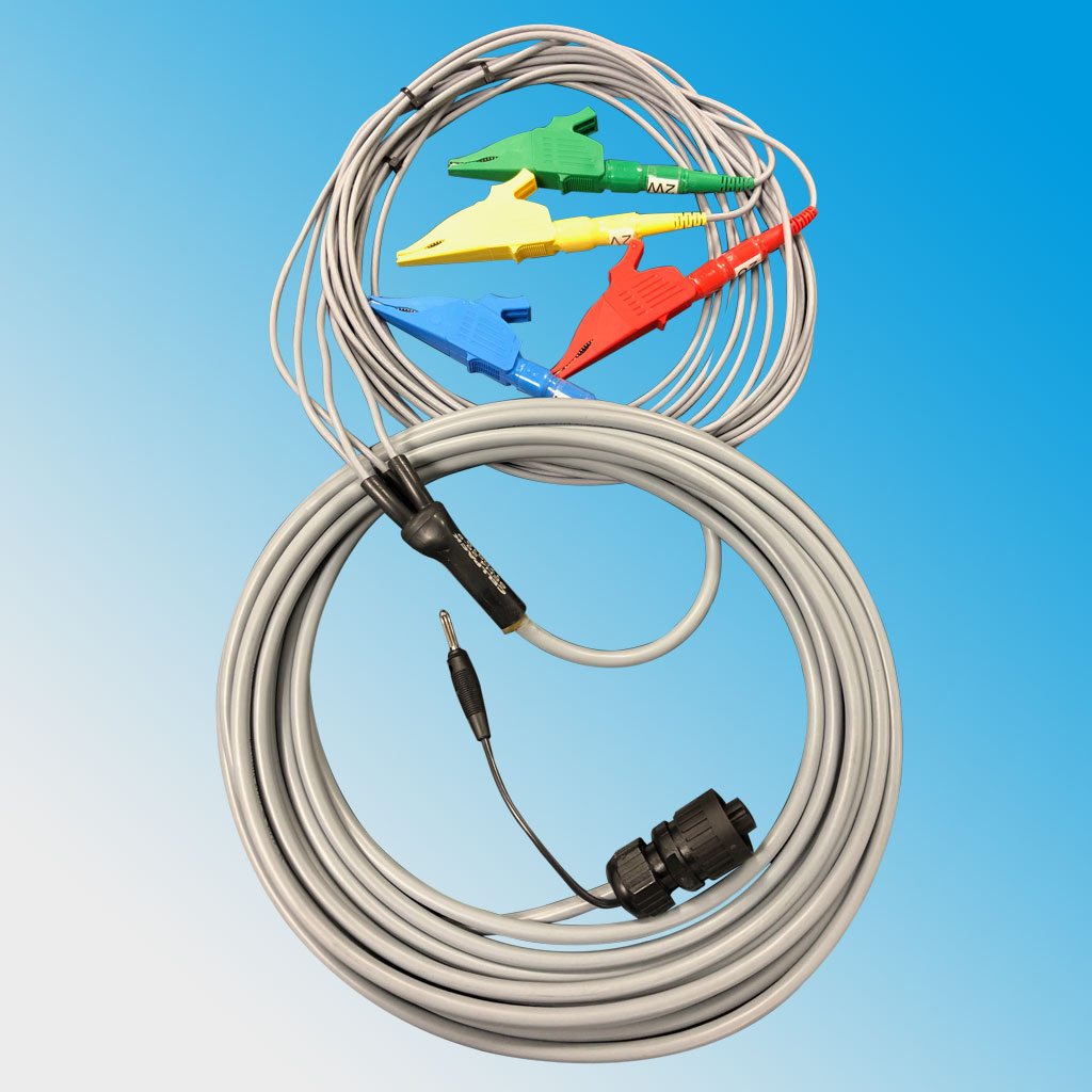
- Cable HV 4pole, various lengths, amphenol jack and clamps (U, V, W, N)
- Cable LV 4pole, various lengths, amphenol jack and clamps (U, V, W, N)
- Calibration certificate
 });
});