Frequency Range4Hz to 40Hz in increments of 0.1Hz
Detector Bandwidth0.5Hz
SensitivityElectrostatic input: 1μV RMS for full scale deflection Auxiliary input: 0μV RMS for full scale deflection
InputImpedance Electrostatic Input: Balanced low impedance Auxiliary input: 10kΩ
Auxiliary Input Connector7 way DIN socket
Electrostatic Input Connector4mm binding post terminals
PowerBuilt-in rechargeable batteries - typically 5 hours continuous use. External Extended battery connection
Mains SupplySingle phase 115V AC to 240V AC
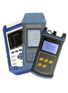
Analogue DisplayAnalogue signal strength meter with battery and signal test
GPSLocation Detection via Inbuilt GPS 4M accuracy
LCDColour LCD with current and historical data, Day/ Night mode
Event markerStored digitally storing Lon,Lat, and signal strength, plus comment
Detection RangeElectrostatic Input: Typically 180 metres but depths of 300 metres are possible. Limited by external factors such as: signal to noise ratio, attenuation of the signal in the cable and lateral distance at which the ship is operating away from the cable Magnetic Detector Inpu: Typically 20 metres but may be limited by external factors such as signal to noise ratio and attenuation of signal in the cable
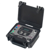
Case TypeDimensions470mm x 360mm x 175mm
WeightApproximately 18Kg
The unit has an inbuilt GPS receiver that tracks its location to an accuracy 4 meters. The received signal is processed and passed to the digital processing system that via the LCD shows the signal strength with automatic gain control. A analogue meter is also available to show the received signal strength. The historical signal strength and GPS Lon,Lat position is stored in memory and can be displayed on the screen allowing operators to locate specific signal conditions and their corresponding Lon, Lat coordinates.
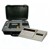
The new digital 5916G has a built-in self test feature, that can be used before each deployment. Normally, the Electroding Generator, Tinsley type 5915, is located in the submarine cable terminal nearest to the fault area. The Electroding Detector, Tinsley type 5916G is aboard the ship. When the ship is in the vicinity of the cable area, the 5915 Electroding Generator is powered thus applying the low frequency signal to the cable under test. At these frequencies, the field of the signal extends into the water surrounding the cable for a considerable distance.
The ship would normally steer a course to cross the cable on the landward side of the expected fault position. Before this position is reached, the ship launches the receiving probes which are connected to the input of the 5916G detector. The Detector is set to the frequency being transmitted by the Electroding Generator on shore. As the ship crosses the cable, the field of the signal current on the cable induces a voltage into the probe/s. This signal is then processed by the Electroding Detector and a deflection on the meter is registered and the system stores the reading and the GPS position. This may also be recorded by the built-in digital chart recorder.
For identification purposes, the Electroding Generator may be keyed on and off periodically. Once the cable signal has been identified and confirmed, the ship then follows the cable on a zigzag course until the signal disappears or is much reduced. When this happens, the fault or break has been passed. Use of NAVSAT on a marker buoy would mark the point where the signal was last detected. Further runs may be made for a more precise fix of the fault position.