


tinsley.co.uk
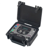
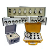
Portable Transformer Ratiometer Model 4167F
Setting up the instrument is a simple case of typing in the vector group using the instrument front panel keypad and connecting to the offline transformer. All three phases are measured consecutively
with connecting and short circuit procedures at the primary and secondary voltage terminals performed automatically before each measurement. It is also possible to measure just one phase if required.
An adjustable set value permits the display of any error or deviation from the required transformation ratio. It is also possible for the 4167F to control the transformer tap changer and in this case all phases and taps are measured consecutively. Results can be stored internally using a transformer specific memory card, printed to an external printer or transferred to a PC via an RS232 interface.
By using a memory card, pre-programmed for a specific transformer type, the instrument can be made to show a PASS / FAIL message with the actual reading.
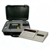
The transformer specific memory cards can be easily programmed via a personal computer using the built in card reader or by a cost efficient external card reader/writer directly connecting to a personal computer.
A market unique feature is the automatic vector group detection. If all connections to the transformer have been made, the correct vector group will be detected. In case of missing a connection (1N or 2N e.g.) there will be up to three possible vector groups displayed to the user. Once the correct vector group has been selected the instruments learns this and that group will be presented first next time.
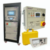
The 4167F is connected to the H.V. and L.V. windings via four connections each. It also powers the transformer at a preset voltage supplied by an internal isolating transformer. However, external excitation using different voltages and frequencies is also possible. is its simplicity to set-up.
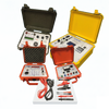
The 4167F is housed in a robust carrying case. All connections are provided at the front panel of the instrument and are locked in order to avoid accidental disconnection during a measurement. An alarm-warning lamp is also available and will illuminate whilst a measurement is in progress.
Accessories
- Warning light: The warning light shows if voltage appears on the test object during measurement.
- Cable HV 4pole, various lengths, amphenol jack and clamps (U, V, W, N)
- Cable LV 4pole, various lengths, Amphenol jack and clamps (U, V, W, N)
- Calibration certificate
Sales & Support
A dedicated support team to support new purchases, technical queries, troubleshooting, and delivery information.
- Features
- Specifications
- Downloads
Product Support
Industry-leading support and diagnostics
Tinsley products are backed by expert technical support, responsive diagnostics and dependable aftersales guidance. From specification advice through to fault-finding and ongoing performance support, our team helps you keep critical equipment operating accurately and reliably.
Expert
Technical assistance, diagnostics insight and practical product support for demanding industrial applications.